Antenna Formulae
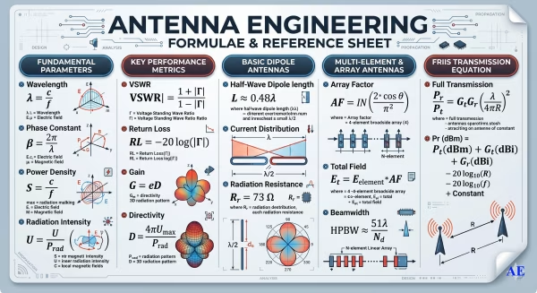
Antenna Formulae & Technical Resources
Radio frequency (RF) antenna design and optimization heavily rely on mathematical equations to predict physical behavior and electrical performance. These core geometric and electromagnetic formulas establish the baseline dimensions required to achieve resonance at specific operational frequencies. Engineers utilize these mathematical relationships to precisely calculate critical performance parameters, including radiation resistance, input impedance, and overall bandwidth capabilities.
By adjusting variables within these equations, designers can tailor the antenna’s directional characteristics to achieve the desired forward gain and front-to-back ratio. Furthermore, these expressions account for velocity factors and structural material properties that inherently alter the effective wavelength of the signal. Accurate mathematical modeling ensures maximum power transfer between the transmitter and the radiating element by minimizing impedance mismatches.
Ultimately, these theoretical calculations serve as the foundation for modern computer-aided simulation tools used in aerospace and defense communications. Consequently, a thorough understanding of these fundamental principles prevents costly trial-and-error iterations during the physical prototyping and manufacturing phases.
Wavelength and Frequency
λ = v / f | Where λ = Wavelength in feet v = Velocity of propagation in feet per second f = Frequency in Hz |
| f = 1 / T | Where f = Frequency in Hz T = Time of one wave period (cycle) in second |
Path Loss and Vertical Dipole Isolation
| Path Loss (dB) = 10log (λ/4πr)2 Isolation (dB) = 28 + 40log (h/λ) | Where λ = Wavelength in metres r = Distance between transmitting and receiving antennas in metres h = Vertical antenna separation |
VSWR, Reflection Coefficient (ρ) and Return Loss
| VSWR = (1 + ρ)/(1 – ρ) | Reflection Coefficient ρ = (VSWR – 1)/(VSWR + 1) |
| Return Loss (dB) = -20 log (ρ) | |
Power Received by an Antenna
P = PtGtGrλ2 / 16π2d2 | Where P = Power received in Watts Pt = Power transmitted in Watts Gt = Gain ratio of transmitting antenna relative to an isotropic radiator Gr = Gain ratio of receiving antenna relative to an isotropic radiator λ = Wavelength in metres d = Distance between transmitting and receiving antennas in metres |
Effective Radiated Power
ERP = G x P | Where G = Gain of transmitting antenna relative to an isotropic radiator P = Input Power in Watts |
VSWR Vs Return Loss and Effect of VSWR on Transmitted Power
| VSWR | Return Loss (dB) | Transmitted Power (%) |
| 1.0 | ∞ | 100 |
| 1.1 | 26.4 | 99.8 |
| 1.2 | 20.8 | 99.2 |
| 1.3 | 17.7 | 98.3 |
| 1.5 | 14.0 | 96.0 |
| 2.0 | 9.50 | 88.9 |
| 3.0 | 6.00 | 75.0 |
dBm to Watts Reference Table
| dBm | Power (Watts) | Description / Typical Application |
|---|---|---|
| 60 dBm | 1,000 W | High-power Broadcast / Large Radar |
| 53 dBm | 200 W | High-power Tactical Jamming Systems |
| 50 dBm | 100 W | Standard Military Base Station Transmitter |
| 47 dBm | 50 W | Medium-power RF Amplifiers |
| 43 dBm | 20 W | Tactical Manpack Radio (VHF/UHF) |
| 40 dBm | 10 W | Standard Telemetry / Long-range IoT |
| 37 dBm | 5 W | High-power Handheld Radios |
| 33 dBm | 2 W | Common Handheld Radio / SATCOM Uplink |
| 30 dBm | 1 W | 1 Watt Reference Level |
| 27 dBm | 500 mW | Low-power Industrial Transmitters |
| 20 dBm | 100 mW | High-power Wi-Fi / Tactical Mesh Nodes |
| 10 dBm | 10 mW | Short-range Telemetry |
| 0 dBm | 1 mW | 1 Milliwatt Reference (Signal Source) |
| -10 dBm | 0.1 mW | Typical Receiver Input Level |
| -30 dBm | 1.00 uW | Low-level Signal Analysis |
Quick "Rule of Thumb" for Conversions
In the field, you can use the Rule of 3s and 10s for rapid estimation:
- +3 dB = Double the Power (x2)
- -3 dB = Half the Power (/2)
- +10 dB = 10 Times the Power (x2)
- -10 dB = 1/10th of the Power (/10)
Example: If your antenna gain is increased by 3 dB, you are effectively doubling your Effective Radiated Power (ERP).
Antenna Isolation is critical to prevent receiver desensitization and interference, especially in military and defense installations where multiple high-power transmitters operate in close proximity.
Typical Vertical Antenna Isolation Requirements by Frequency
The following table outlines the approximate physical separation required to achieve 30 dB and 50 dB of isolation for vertical antennas (center-to-center).
| Frequency Band | Frequency (MHz) | 30 dB Isolation (h) | 50 dB Isolation (h) | Typical Application |
|---|---|---|---|---|
| HF | 30 MHz | ~11.5 meters | ~36.0 meters | Tactical HF Whip |
| VHF (Low) | 88 MHz | ~4.0 meters | ~12.5 meters | FM Broadcast / Public Safety |
| VHF (High) | 150 MHz | ~2.3 meters | ~7.2 meters | Marine / ATC / LMR |
| UHF | 450 MHz | ~0.8 meters | ~2.4 meters | TETRA / SCADA / UHF Link |
| L-Band | 1200 MHz | ~0.3 meters | ~1.0 meters | GNSS / SATCOM / Radar |
| S-Band | 2400 MHz | ~0.15 meters | ~0.5 meters | 5G / ISM / S-Band Telemetry |
Key Factors Influencing Isolation
- Vertical vs. Horizontal Separation: Vertical separation (stacking antennas on top of each other) provides significantly higher isolation than horizontal separation at the same distance due to the "nulls" in the vertical radiation pattern.
- Polarization: Cross-polarization (e.g., one Vertical and one Horizontal antenna) can add an additional 15–20 dB of isolation.
- Antenna Gain: High-gain directional antennas (like Yagis) pointed away from each other significantly increase isolation compared to omnidirectional antennas.
- Near-Field Effects: At very close distances (less than 2 wavelengths), standard path loss formulas may not be accurate, and empirical testing with a VNA (Vector Network Analyzer) is required.
Typical Horizontal Antenna Isolation (dB) vs. Distance
This table provides the isolation achieved (in dB) at specific horizontal distances (R) for common frequency bands.
| Frequency Band | 1 Meter (r) | 3 Meters (r) | 5 Meters (r) | 10 Meters (r) | Application Context |
|---|---|---|---|---|---|
| VHF (150 MHz) | ~16 dB | ~25 dB | ~30 dB | ~36 dB | Marine / LMR / ATC |
| UHF (450 MHz) | ~25 dB | ~35 dB | ~40 dB | ~46 dB | TETRA / Public Safety |
| GSM (900 MHz) | ~32 dB | ~42 dB | ~46 dB | ~52 dB | Cellular / SCADA |
| L-Band (1.5 GHz) | ~36 dB | ~46 dB | ~50 dB | ~56 dB | SATCOM / GNSS |
| S-Band (2.4 GHz) | ~40 dB | ~50 dB | ~54 dB | ~60 dB | Wi-Fi / ISM / Telemetry |
| C-Band (5.8 GHz) | ~48 dB | ~58 dB | ~62 dB |
Practical Design Considerations
- The "Rule of 6 dB": Doubling the horizontal distance between two antennas typically increases the isolation by approximately 6 dB.
- Pattern Nulls: If using directional antennas, rotating them so they are "back-to-back" can increase isolation by the Front-to-Back (F/B) ratio of the antennas (often adding 15–25 dB of isolation).
- Shielding: Placing a physical metallic barrier or the tower structure itself between two antennas can provide a "shadowing" effect, significantly increasing horizontal isolation.
Practical Overview of Antenna Parameters
Understanding key antenna parameters is essential for selecting and using antennas in virtually all applications. These applications include antenna testing, electromagnetic compatibility (EMC), FCC/IEC compliance testing, telecommunications, internet of things (IoT) and more. There are a variety of standardized methods for describing antenna parameters, and this article aims to provide an overview of key antenna parameters and relevant background.
Common Antenna Parameters
Antennas are used in all wireless systems from IoT devices to microwave and millimeter-wave imaging systems, such as radio telescopes. Antennas are the key element in a wireless system that converts electron flow to electromagnetic radiation in a symmetric manner that is carefully designed. The exact behavior of an antenna is related to the geometry of the conductors and dielectrics in its structure, and there are a wide variety of antennas to accommodate various application requirements.
There are two main categories of antenna behavior: radiation parameters and network parameters. These parameters are typically only given for the frequencies within an antenna’s bandwidth. The bandwidth of an antenna is merely the range of frequencies for which the manufacturer has specified. Antennas typically exhibit broadband behavior that may extend beyond the antenna’s bandwidth.
Radiation parameters describe the functioning of the antenna as it converts electromagnetic energy to electronics and vice versa. Network parameters describe the behavior of an antenna's interconnect and ports with which an antenna is connected to transmitters, receivers, interconnect and measurement devices.
Radiation Parameters
When electrons produced by a time varying signal with sufficient high frequency components pass through a conductor that is not shielded, the result is the creation of an electromagnetic wave, or the antenna radiation. A specific distance away from an antenna where the electric and magnetic fields of the electromagnetic radiation pattern from the antenna are perfectly orthogonal is called the far field of an antenna. The parameters of an antenna are typically measured in the far field. The behavior of an antenna’s radiation is described by several key parameters, which are discussed in the following section.
Radiation Pattern
The radiation pattern of an antenna is determined by the three-dimensional shape of the antenna’s far-field radiation. The mounting of the antenna is a critical aspect of radiation parameters, so some guidance should be given on the intended orientation of an antenna to best understand an antenna’s radiation pattern. Given a coordinate system where x and y make the azimuthal plane and z is the elevation plane, an antenna’s pattern is determined by the strength of the radiation in three-dimensional space.
There are essentially three different types of antenna radiation patterns: isotropic, omnidirectional and directional. An isotropic antenna pattern radiates power equally in all directions and is only a theoretical antenna pattern used as a tool to compare and measure actual antenna patterns. An omnidirectional antenna pattern is roughly constant in the azimuthal plane but varies in power in the elevation plane, such as a dipole or small loop antenna. A directional antenna, on the other hand, dominantly radiates energy in one or more directions.
Front to Back Ratio
The front to back (F/B) ratio is a measure of the power radiated from the primary (front) lobe and the power radiated 180° in the opposite direction of the primary lobe (in dB). As typical with directional antennas, the primary lobe is the only desired lobe, and any other power radiated in other lobes is non-ideal. The F/B ratio can be used to compare antennas based on the amount of backward radiation an antenna generates.
Antenna Polarization
Antenna polarization is a description of the way the electric field (E-field) or magnetic field (H-field) of a wavefront oscillates. If the field lines oscillate within a single axis, they are known as linearly polarized. A linear polarized antenna may be horizontal (0°), vertical (90°) or cross polarized if at an angle other than 0° or 90°. An elliptical polarization is when the field oscillations of the wavefront orbit around the origin and are either traveling clockwise (right hand elliptically polarized) or counterclockwise (left hand elliptically polarized). As a special case of elliptical polarization, the E-field lines may perfectly rotate around the origin and form a circle, which is known as circular polarization.
Antenna Directivity
The directivity of an antenna is the measurement of the highest amount of radiated power in a direction divided by the average power of an antenna radiated in all directions. Hence, a high directivity antenna will have a beam pattern that is very strong in a single direction, where an antenna with lower directivity will have greater amounts of beam energy outside of the main lobe. The envelope of an antenna may also be described in terms of the half power beamwidth, otherwise known as the 3 dB beamwidth. The 3 dB beamwidth is the angular width of the radiation pattern between the two points 3 dB below the peak beam.
Antenna Gain (dBi) Efficiency
Antenna gain is a relative parameter that describes the amount of power transmitted in the main direction of the antenna in respect to an isotropic radiating source. For instance, an antenna with a 6 dB antenna gain would receive 6 dB greater power than an isotropic antenna in the same position. Antenna gain may also be given in terms of dBi, which is dB relative to an isotropic antenna, but may also be given as dBd, which is dB relative to a dipole antenna (2.15 dBi).
This is not to be confused with antenna efficiency, which is a ratio of the power input to an antenna compared to the amount of power radiated from an antenna. Efficiency is often given as a percentage, a decimal or in dB, but is just a ratio with a value between zero and one. Antenna efficiency should also not be confused with antenna voltage standing wave ratio (VSWR) or reflection coefficient, which is related to the impedance match of the antenna ports to the interconnect and/or source. An antenna may be measured in terms of total efficiency, which is merely a multiplication of antenna radiation efficiency and loss from impedance mismatch.
Antenna Correction Factor
Antenna factor, or antenna correction factor, is a ratio of the incident electromagnetic field to the output voltage from the antenna and the output connector. The antenna factor is a function of frequency, and the relationship between voltage developed at the antenna port and an antenna’s radiated field intensity is important for radio frequency interference and electromagnetic interference (RFI/EMI) and antenna characterization.
Near Field vs Far Field
The antenna parameters discussed previously are all given for an antenna’s far field. Within a few wavelengths of an antenna, however, the behavior of the electromagnetic radiation around an antenna is quite different. The near field is composed of two regions, the non-radiative (reactive) and the radiative (Fresnel) region. The reactive region, the electric and magnetic field strength decrease by the inverse cubed law with distance, compared to the radiative region decreasing as an inverse square law with distance. Hence, the near field drops off much more rapidly than the far field and is only relevant for antenna systems with objects in near proximity to the antenna.
Knowledge of the near field dynamics are important, as absorption of radiation in the near field changes the antenna behavior as seen by the transmit and receive hardware. Moreover, interactions between an antenna and other objects in the near field can result in a distortion of the far field radiation and undesirable effects.
Wireless Network Parameters
The network parameters of an antenna are used to determine the appropriate matching network and interconnect needed to connect an antenna to a transmitter/receiver. For more complex antenna types, an antenna’s network parameters are also used to design the algorithms and RF circuits used to drive the antenna.
Input Impedance
The input impedance of an antenna is a ratio of the complex, input (source) voltage and current at the antenna port. In the case of many antenna designs, the raw antenna impedance is not matched to common transmission line impedances, such as 50 ohms or 75 ohms coaxial transmission lines or waveguide interconnect. Hence, a matching network is used to transform an antenna's innate impedance to the impedance of the transmission line, waveguide, or directly to the transmitter/receiver front-end. How well an antenna impedance is matched to a desired port impedance is given as a VSWR and reflection coefficient measurement.
Reflection Coefficient
The reflection coefficient is a measure of the ratio of the power of a forward signal that is reflected from a port compared to the total power of the signal minus what is lost as radiation. In terms of characteristic impedance to load impedance, the reflection coefficient is mathematically determined using the following equation: 𝚪 = ZL - Z0/ZL+Z0
here 𝚪 is the reflection coefficient, ZL is the load impedance, and Z0 is the characteristic impedance of the transmission line or waveguide. For maximum energy transfer, it is desirable to have a reflection coefficient as close to zero as possible. The VSWR is mathematically derived from the reflection coefficient.
VSWR
The VSWR, also known as standing wave ratio (SWR), is the ratio of the maximum voltage and minimum voltage of a standing wave developed at the port of an antenna. For the most efficient transmission and reception, an ideal antenna has a VSWR of 1:1. Any imperfection in the antenna design or antenna port/feed that results in an impedance mismatch leads to a degraded VSWR where some of the RF energy is reflected from the antenna port and the transmitter/receiver ports.
Antenna Element Mutual Coupling and Isolation
In the case of antenna arrays, multimode antennas or multi-polarized antennas, there will be some electric and magnetic coupling between the antennas or ports. The isolation between the elements is a measure of the signal strength in a given element and the strength of that signal coupled into another element. The isolation is usually given as a worst-case figure, but often must be characterized in order to implement multi-input multi-output (MIMO) or beamforming algorithms.
Network Characterizations
Antenna may also be described in terms of network characterization parameters, such as Z-parameters, S-parameters or ABCD-parameters. This is typically done in the process of antenna characterization, and an antenna’s datasheet may contain some network characterization parameters as they are typical of how components with frequency dependent behavior are measured using vector network analyzers.
Conclusion
This article provided a basic discussion of common antenna parameters, both radiation and network parameters. With this knowledge a reader should be able to better evaluate the viability of an antenna for a given application. For more information on antennas, visit https://www.antennaexperts.com/
