Antenna Glossary
Comprehensive Military Antenna Glossary: Essential RF & Defense Terms
Welcome to the Antenna Experts Military Antenna Glossary. Navigating the world of defense communications, electronic warfare (EW), and signal intelligence (SIGINT) requires a specialized vocabulary. Whether you are a procurement officer sourcing high-performance tactical antennas, or an RF engineer designing an Electronic Countermeasure (ECM) system, this glossary provides clear, industry-standard definitions for the most critical military antenna terminology.
A-E: Core Antenna & Defense Concepts
- Attenuation: The gradual loss of signal strength (RF energy) as it travels through a medium, such as cables or the atmosphere.
- Broadband Antenna: An antenna designed to operate over a wide range of frequencies without requiring physical adjustments or tuning. Crucial for frequency-hopping military radios and ECM jamming systems.
- C-Band: A portion of the electromagnetic spectrum (typically 4 to 8 GHz) heavily used for military satellite communications (SATCOM) and secure radar systems.
- COTS (Commercial Off-The-Shelf): Standardized, commercially available products (including antennas) that can be adapted for military use to reduce development time and costs.
- Dipole Antenna: A fundamental antenna design consisting of two conductive elements. It is the building block for many complex tactical antennas.
- Direction Finding (DF) Antenna: Specialized antenna arrays used in Signal Intelligence (SIGINT) to determine the geographical origin of an enemy's radio frequency signal.
- Discone Antenna: A biconical, broadband, omnidirectional antenna commonly used in military aviation, ATC (Air Traffic Control), and tactical ground communications due to its exceptionally wide frequency range.
- ECCM (Electronic Counter-Countermeasures): Techniques and hardware (like frequency-hopping antennas) used to protect allied communications from enemy jamming and interception.
- ECM (Electronic Countermeasures): The use of RF energy to jam, deceive, or disrupt enemy communications and radar. Jamming Antennas are the primary delivery method for ECM.
- EW (Electronic Warfare): The overall use of the electromagnetic spectrum to deny its use by an adversary, while protecting its use for friendly forces.
F-M: Frequencies, Gain, & Tactical Gear
- Frequency Hopping: A secure communication method where the transmission frequency changes rapidly in a pseudo-random sequence. Requires a highly efficient Broadband Antenna to function seamlessly.
- Gain (dBi / dBd): A measure of an antenna's ability to direct or focus RF energy in a specific direction compared to a standard reference (isotropic or dipole). High-gain antennas provide longer-range communication.
- HF (High Frequency): The 3 to 30 MHz range. Used in the military for Beyond Line-of-Sight (BLOS) communication, utilizing the ionosphere to bounce signals over the horizon.
- Jamming Antenna: High-power, extremely robust antennas designed to blast RF noise across specific frequency bands to disable enemy IEDs, drones, or communications.
- Log Periodic Dipole Array (LPDA): A highly directional, broadband antenna. Often used in military base stations and EW applications for secure, point-to-point communications over a massive frequency range.
- Manpack Antenna: Lightweight, rugged, and portable antennas designed to be carried by infantry soldiers. Usually attached to tactical backpack radios operating in the VHF/UHF bands.
- Monopole Antenna: A single-element antenna, typically mounted vertically over a ground plane (like a military vehicle's roof). Ideal for mobile tactical communications.
O-Z: Advanced Arrays & Performance Metrics
- Omnidirectional Antenna: An antenna that radiates and receives RF energy equally in all horizontal directions (360 degrees). Essential for mobile mesh networks and command post communications.
- Phased Array: A complex antenna system composed of multiple radiating elements. The beam direction can be electronically steered without physically moving the antenna, vital for modern radar and missile defense.
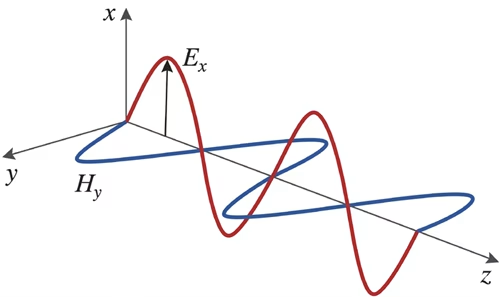
- Polarization: The orientation of the electromagnetic wave's electric field. Military antennas can be vertically, horizontally, or circularly polarized, depending on the operational requirement and environment.
- SATCOM (Satellite Communications): Antennas designed to transmit and receive secure data, voice, and video to and from military satellites in orbit.
- Tactical Antenna: A broad category of extremely durable antennas built to MIL-STD (Military Standard) specifications to withstand harsh combat environments, extreme weather, and rough handling.
- UHF (Ultra High Frequency): The 300 MHz to 3 GHz range. Heavily used for ground-to-air tactical comms, secure handheld radios, and drone datalinks.
- VHF (Very High Frequency): The 30 MHz to 300 MHz range. The backbone of short-to-medium range tactical ground communications for infantry and armored vehicles.
- VSWR (Voltage Standing Wave Ratio): A critical metric of antenna efficiency. It measures how well the antenna is matched to the radio transmitter. A lower VSWR (e.g., < 2.0:1) means more power is transmitted and less is dangerously reflected back into the radio.
- Yagi-Uda Antenna: A directional antenna consisting of a driven element and multiple parasitic elements (reflectors and directors). Used for high-gain, point-to-point military networks.
Essential RF and Antenna Glossary & Terminology
A
- Active Antenna: An antenna system that integrates active electronic components, such as low-noise amplifiers (LNAs) or power amplifiers, directly onto the antenna structure to improve signal-to-noise ratio or boost transmit power before cable loss occurs.
- Active Electronically Scanned Array (AESA): A type of phased array antenna in which each antenna element has its own solid-state transmitter/receiver module, allowing for independent computer-controlled steering of multiple radio wave beams without moving parts.
- Anechoic Chamber: A specialized, shielded room lined with RF-absorbing material (usually carbon-infused foam pyramids) designed to completely absorb reflections of electromagnetic waves, creating a controlled environment for testing antenna radiation patterns and EMI/EMC compliance.
- Attenuation: The reduction in amplitude and intensity of an electromagnetic signal as it transmits through a medium (like air, cables, or waveguides), typically measured in decibels per meter (dB/m) or as a total loss in dB.
- Azimuth: The horizontal angular distance or direction of an antenna's beam, measured in degrees clockwise from a reference point (usually True North) in a horizontal plane.
B
- Bandwidth: The range of frequencies over which an antenna or RF component maintains acceptable performance characteristics, such as VSWR, gain, or radiation pattern, typically defined by upper and lower frequency limits (f_{high} - f_{low}).
- Beamwidth (HPBW): Half-Power Beamwidth. The angular width of the main radiation lobe between the two points where the power density drops to half (-3dB) of its maximum value. It defines the directional sharpness of the antenna.
- Bi-directional Antenna: An antenna designed to radiate or receive electromagnetic energy efficiently in two opposite directions (e.g., a standard dipole antenna).
C
- Circular Polarization (CP): An electromagnetic wave polarization where the electric field vector rotates in a circular motion perpendicular to the direction of propagation. It can be Right-Hand Circularly Polarized (RHCP) or Left-Hand Circularly Polarized (LHCP), heavily utilized in SATCOM to mitigate ionospheric Faraday rotation.
- Coaxial Cable: A two-conductor transmission line consisting of a central inner conductor surrounded by a concentric dielectric spacing material, which is wrapped in an outer cylindrical conductor (shield/braid) and protected by an insulating jacket.
- Cross-Polarization Discrimination (XPD): The ratio of the power received in the co-polarized wave to the power received in the cross-polarized wave, indicating how effectively an antenna can isolate orthogonally polarized signals.
D
- dB (Decibel): A logarithmic unit used to express the ratio of two values of a physical quantity, often power or intensity.
- dBd: Antenna gain relative to a standard, ideal half-wave dipole antenna. 0dBd = 2.15dBi
- dBi: Antenna gain relative to an ideal isotropic radiator (a theoretical antenna that distributes energy equally in all directions).
- dBm: A logarithmic unit of power relative to 1 milliwatt (0dBm = 1mW).
- Directivity: The ratio of the radiation intensity of an antenna in a given direction to the average radiation intensity over all directions. It measures how focused the electromagnetic energy is, ignoring internal thermal losses.
- Discone Antenna: A type of omnidirectional, ultra-wideband (UWB) biconical antenna consisting of a flat disc mounted horizontally on top of a conductive cone. Highly valued in SIGINT and tactical monitoring due to its massive frequency coverage.
E
Effective Isotropically Radiated Power (EIRP): The hypothetical total power that would have to be radiated by an isotropic antenna to give the same signal strength as the actual antenna in the direction of its maximum gain.
EIRP = Tx Power (dBm) - Cable Loss (dB) + Antenna Gain (dBi)
Electromagnetic Interference (EMI): Disturbance generated by an external source that affects an electrical circuit by electromagnetic induction, electrostatic coupling, or conduction, degrading RF system performance.
- E-Plane: The plane containing the electric field vector and the direction of maximum radiation of an antenna.
F
- Fading: Fluctuations in signal strength at a receiver caused by changes in the transmission medium, atmospheric conditions, or multi-path interference where signals bounce off obstacles and arrive out of phase.
Far-Field (Fraunhofer Region): The region far from the antenna where the wave front becomes essentially planar and the angular radiation pattern does not change with distance. It typically begins at a distance defined by:
R = 2D^2\lambda
where D is the largest dimension of the antenna and lambda is the wavelength.
- Front-to-Back Ratio (F/B): The ratio of power radiated in the maximum directional peak to that radiated in the exact opposite direction (180 Degrees away), expressed in decibels (dB). High F/B ratios minimize backward interference.
G
- Gain: The combination of an antenna's directivity and its electrical efficiency. It quantifies how much of the input power is transformed into RF waves in a specified direction compared to an isotropic source (dBi) or a dipole (dBd).
- Ground Plane: A flat or structured conductive surface positioned beneath or around an antenna element that acts as a mirror for radio waves, creating a virtual image of the antenna to complete the RF circuit (essential for monopoles).
H
- Helical Antenna: An antenna consisting of a conducting wire wound in the form of a helix. Operating in axial mode, it yields high directivity and circular polarization, which is ideal for satellite and space communication.
- H-Plane: The plane containing the magnetic field vector and the direction of maximum radiation of an antenna, perpendicular to the E-plane.
I
- Impedance (Z): The total opposition offered by a circuit to the flow of alternating current, consisting of resistance (R) and reactance (X), expressed as Z = R + jX. In standard RF and microwave equipment, the nominal system impedance is almost universally 50 Ohms.
- Insertion Loss: The total loss of signal power resulting from the insertion of a component (like a filter, cable, or connector) into an RF transmission line, measured in dB.
- Isotropic Radiator: A theoretical, lossless antenna that radiates electromagnetic energy uniformly and equally in all directions (360 degrees spherical coverage). It has a gain of 0 dBi and serves as a baseline reference.
L
- Lightning Protection: Mechanisms integrated into antennas or transmission paths (such as DC-grounded elements or gas discharge surge arrestors) designed to divert high-voltage lightning surges safely to the earth ground, protecting sensitive transceiver equipment.
- Log-Periodic Antenna (LPDA): A directional, broadband directional antenna consisting of a series of dipoles of graduated lengths. It offers stable gain and impedance characteristics over exceptionally wide frequency bandwidths.
M
- Main Lobe: The radiation lobe containing the direction of maximum radiation intensity from the antenna.
- Monopole Antenna: A class of radio antenna consisting of a single straight rod-shaped conductor, often mounted perpendicularly over a conductive ground plane. It behaves like a half-wave dipole using its ground image.
N
- Near-Field (Fresnel & Reactive Regions): The region closest to the antenna element where the electric and magnetic fields are highly complex, reactive, and do not yet form a propagating plane wave. Radiation patterns measured here change drastically with distance.
O
- Omnidirectional Antenna: An antenna that radiates or receives radio frequency energy equally in all directions within a single plane (typically the horizontal plane, creating a donut-shaped radiation pattern).
P
- Phased Array: An array of multiple antenna elements in which the relative phases of the feeding signals are intentionally varied to electronically steer the radiation beam direction without physical movement.
- Polarization: The orientation of the electric field E field vector of an electromagnetic wave as it travels through space. Common types include Vertical, Horizontal, Linear, and Circular (LHCP/RHCP). Matching polarization between transmitting and receiving antennas is critical to avoid polarization mismatch loss.
Q
- Quadrifilar Helix Antenna (QHA): An antenna consisting of four orthogonal helical tracks fed with precise 90 degrees phase shifts. It provides an omnidirectional circular polarization with high hemispherical coverage, highly effective for GPS and meteorological satellite tracking.
R
- Radome: A rugged, weatherproof, and RF-transparent protective enclosure used to shield an antenna assembly from environmental elements (wind, ice, rain, UV radiation) without degrading its electrical performance.
- Return Loss: A measure of how much power is reflected back toward the source due to an impedance mismatch in the transmission line, expressed as a positive value in dB. A higher return loss indicates a better-matched system (e.g., 20 dB is excellent, 10 dB is acceptable).
S
- Side Lobes: Unintentional lobes of radiation extending from an antenna in directions other than the desired main lobe. Lower side lobes minimize interference and signal wastage.
- SIGINT (Signals Intelligence): A category of intelligence-gathering by intercepting electronic signals, utilizing highly specialized, ultra-wideband antennas to monitor and analyze communications and radar signatures.
T
- TETRA (Terrestrial Trunked Radio): A European standard for a professional mobile radio and two-way transceiver system designed for critical public safety, military, and emergency services. It utilizes specialized, highly ruggedized antennas typically operating in the 300–450 MHz bands.
V
- Velocity Factor (VF): The speed at which an electromagnetic wave travels through a transmission line (like a coaxial cable) relative to the speed of light in a vacuum (c). It is expressed as a percentage or fraction (e.g., .66 or 66%).
- VSWR (Voltage Standing Wave Ratio): A measure of how efficiently radio-frequency power is transmitted from a power source through a transmission line into a load (the antenna). It indicates the severity of standing waves caused by impedance mismatches.
- A VSWR of 1.0:1 is a perfect match (zero reflection).
- A VSWR of 1.5:1 or lower is typical for high-performance defense and industrial antennas.
W
- Waveguide: A hollow, metal conductive tube or pipe engineered to guide high-frequency microwave signals with extremely low attenuation and high power-handling capabilities, replacing coaxial cables at higher frequencies.
Wavelength (lambda): The physical distance between two successive crests or identical points of an electromagnetic wave cycle in a given medium. Calculated via:
lambda = v/f
where v is the phase velocity and f is the frequency.
Looking for field-proven tactical antennas?
At Antenna Experts, we design and manufacture military-grade antennas for EW, SIGINT, ECM, and tactical communications that meet the most demanding global defense standards.
Basic Antenna Glossary
Antenna: A metallic device used in the transmission and reception of electromagnetic waves. An antenna is a passive or an active device which permits transmission.
Antenna Power Gain: The ratio of the antenna’s maximum radiation intensity in a stated direction to the maximum radiation intensity of a reference antenna (dipole, isotropic antenna) with identical power applied to both.
Attenuation: The loss in power of electromagnetic signals between transmission and reception points.
Azimuth: Horizontal direction expressed as the angular distance between the direction of a fixed point (as the observer’s heading) and the direction of the object.
Bandwidth: A range of consecutive frequencies comprised of a band (i.e. the US cellular bandwidth is 72 MHz wide between the frequencies of 824 MHz – 894 MHz) over which an antenna shall perform without the need of any adjustment.
Base Station: In a cellular communication system, a base station could be considered a central mode of transmission and reception for the network. Currently, this station includes an omnidirectional antenna or several sectoral antennas.
Beamwidth: The angle of signal coverage provided by an antenna. Beamwidth typically decreases as antenna gain increases.
Cable Loss: A numeric value describing the amount or signal loss from one point on a length of cable to another. This is measured in decibels (dB).
Center Fed: Transmission line connection at the electrical center of an antenna radiator.
Coaxial Cable: Cable consisting of a single copper conductor in the center surrounded by a plastic layer for insulation and a braided metal outer shield. Coax is used to transfer radio frequency energy from the transmitter to the antenna.
Collinear Array: A system of two or more antenna radiators arranged in a line and connected end-to-end to generate a directed field pattern (serial linear topology).
Coupler: Referring to on-glass antennas, a coupler is the two-piece interface between the coaxial cable on the inside of the glass and the radiator on the outside of the vehicle. It is designed to efficiently couple RF energy through the glass. The formulation of the glass and glass thickness normally have a substantial effect on coupler performance.
dBd: Quantification of the gain for an antenna in comparison with the gain of a dipole.
dBi: The dB power relative to an isotropic source.
dBm: A measure of power based upon the decibel scale, but referenced to the milliWatt: i.e. 1dBm = .001 Watt. dBm is often used to describe absolute power level where the point of reference is 1 milliWatt. In high power applications the dBW is often used with a reference of 1 Watt.
dBW: The ratio of the power to one Watt expressed in decibels.
DC Ground: An antenna which is a dead short to a DC current, and has a shunt fed design. To RF it is not seen as a short.
Dipole: An antenna — usually a half wavelength long — split at the exact center for connection to a feed line.
Directional Antenna: An antenna having the property of radiating or receiving electromagnetic waves more effectively in some directions than others.
Directivity: The theoretical characteristic of an antenna to concentrate power in only one direction, whether transmitting or receiving.
Driven Element: A radiator element of an antenna system to which the transmission line is connected.
Efficiency: The ratio of useful output to input power, determined in antenna systems by losses in the system including losses in nearby objects.
Electrically Small Antenna: Some antennas (such as various low profile antennas, some base loaded whips and often rubber duckie portable antennas) are physically considerably smaller than either a 1/2 or 1/4 wavelength antenna. The challenge with electrically small antennas is to maintain radiating efficiency. A greater challenge is to design an antenna with adequate bandwidth. Careful design using high quality materials often overcome these obstacles.
Embedded Antennas: Antennas directly integrated into a system such as an access point, a terminal or a handset. In most cases, this antenna is matched to the system and can not be used in other applications without modification.
E-Plane and H-Plane: Antenna measurements in general and radiation patterns in particular must be performed with polarization in mind. Since polarization is defined as having the same orientation as an antenna’s electric field vector, it is common practice to refer to measurements aligned with either the electric vector ( E-plane) or magnetic vector (H-plane).
ERP: Effective Radiated Power.
Fiber Optic Cable: A cable, consisting of a center glass core surrounded by layers of plastic that transmits data using light rather than electricity. It has the ability to carry more information over much longer distance.
Field Strength: An absolute measure in one direction of the electromagnetic wave field generated by an antenna at some distance away from the antenna.
Frequency: The number of cycles per second of a wave.
Front-To-Back Ratio: The ratio of radiated power off the front to the back of a directive antenna. A dipole would have a ratio of 1, for example.
Full Duplex: Refers to a communication system or equipment capable of transmission and reception simultaneously.
Gain: Gain is the practical value of the directivity of an antenna. It takes into account the efficiency of the complete structure.
Gigahertz (GHz): One billion cycles per second.
GPS: Global Positional Satellite or Global Positioning System.
Ground Plane: A man made system of conductors placed below an antenna to serve as an earth ground.
Hertz (Hz): A unit of frequency equal to one cycle per second.
Impedance: The Ohmic value of an antenna feed point, matching section or transmission line at a radio frequency. An Impedance may contain a reactance as well as a resistance component.
Lightning Protector: A device designed to divert large surges of current such as a lightning strike from reaching the RF equipment. There are many types of lightning protectors including Quarter Wave Stub and Gas Discharge Tubes.
Load: The electrical entity to which power is delivered. The antenna system is a load for a transmitter.
Megahertz (MHz): 1 million cycles per second.
Mount: A mount is the device onto which a mobile antenna attaches. It is the mechanical and electrical interface between an antenna and the vehicle.
Noise: Any unwanted and un-modulated energy that is always present to some extent within any signal.
Omnidirectional: An antenna providing a 360-degree transmission pattern. This type of antenna is used when coverage in all directions is required.
Parabolic Antenna: An antenna consisting of a parabolic reflector and a radiating or receiving element at or near its focus. Parabolic antennas are very directive and includes a preliminary source and a parabolic reflector to focus the energy.
PCB: Printed Circuit Board.
Planar Array: An antenna in which all of the elements, both active and parasitic, are in one plane.
Point-to-Point: A communications channel running from one point to another.
Point-to-Multipoint: A communications channel running from one point to several other points.
Polarization: The sense of the wave radiated by an antenna. This can be horizontal, vertical, elliptical or circular (left or right hand circularity) depending on the design and application.
Radiation Pattern: The graphical representation of the relative field strength radiated from an antenna in a given plane, plotted against the angular distance from a given reference.
Radiator: A discrete conductor radiating RF energy in an antenna system.
Radome: A typically rigid dielectric cover over the radiating portion of an antenna, and nearly always separated from the radiator by an air gap. A radome (the merger of radar and dome) has the purpose of protecting the radiator from natural weather phenomena and contamination by dirt. It usually includes aerodynamic shaping to minimize wind loading.
Receiver (Rx): An electronic device which enables a particular signal to be separated from all and converts the signal format into a format for video, voice or data.
Relative Antenna Power Gain: The ratio of the average radiation intensity of the test antenna to the average radiation of a reference antenna with all other conditions remaining equal.
RFDC: Radio Frequency Data Communications.
RFID: Radio Frequency IDentification.
RSSi: Received Signal Strength Indicator. Provides a signal for logic circuit processing that is a function of received RF signal strength. RSSI is used both by the switch and the mobile or portable.
Standard Impedance: The nominal impedance associated with the transmission line and test equipment.
Transmission Line: The connecting link allowing the radio frequency energy generated by the radio to be delivered to the antenna. (Coaxial cable, microstrip or coplanar lines in our industry.)
Transmitter : An electronic device consisting of oscillator, modulator and other circuits which produce a radio electromagnetic wave signal for radiation into the atmosphere by an antenna.
Voltage Standing Wave Ratio (VSWR): VSWR of the antenna is the ratio of the maximum to minimum values of voltage in the standing wave pattern appearing along a lossless 50 Ohms transmission line with an antenna as the load.
