Design Diagrams
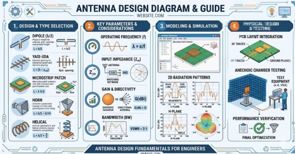
Design Diagrams of Different Types of RF Antennas
Understanding the complexities of Radio Frequency (RF) engineering begins with a clear visual foundation. Our comprehensive collection of design diagrams of different types of RF antennas offers engineers, hobbyists, and students an intuitive look into electromagnetic wave propagation and structural layouts.
From the simple geometry of a classic dipole antenna diagram to the intricate, mission-critical military antennas, these technical schematics break down critical parameters like radiation patterns, impedance matching networks, and feed mechanisms. Whether you are analyzing the directional gain of a yagi antenna, horn antenna, spiral antenna or exploring the wideband capabilities of a log-periodic antenna, military discone antenna, UHF Satcom antenna, tactical radio relay antenna, ATC & Aviation, these high-quality RF schematics serve as an essential blueprint for optimizing signal strength, minimizing return loss, and mastering modern wireless communication systems.
Please refer to our “Knowledgebase” section of our website for more technical details like Antenna Glossary, Tech Library, FAQ, Antenna Formulae and Technical Charts.
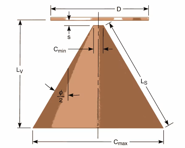
Military-Grade Discone Antennas Design & Diagram
The military discone antenna is a specialized wideband radiator designed for high-performance communication and surveillance across vast frequency ranges, typically spanning from VHF to UHF. Its unique geometry—consisting of a horizontal disc and a downward-slanting conical skirt—allows for a constant impedance and a stable omnidirectional radiation pattern without the need for an antenna tuner. This design is particularly advantageous for Electronic Warfare (EW), SIGINT, and tactical base station applications where rapid frequency hopping and multi-band interoperability are critical.
Built to withstand rigorous field conditions, these antennas are constructed from high-strength materials like aviation-grade aluminum or stainless steel, finished with MIL-SPEC coatings such as Olive Green or Desert Tan for environmental protection and low visibility. The discone’s inherent ability to handle both vertical polarized signals ensures reliable link margins for ground-to-air and ground-to-ground communication in the most challenging operational theaters.
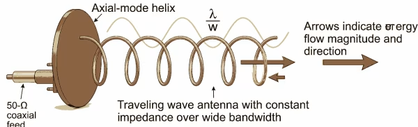
High-Gain Circular Polarized Helical Antennas Design & Diagram
Circularly polarized helical antennas are essential for satellite communications and long-range telemetry where signal orientation can be unpredictable. By winding a conductor in a precise helix over a ground plane, these antennas generate a beam with either Right-Hand (RHCP) or Left-Hand (LHCP) circular polarization. This design is inherently robust against Faraday rotation and multipath interference, ensuring a stable link even as satellites rotate or signal reflections occur.
When operating in axial mode, the helical antenna provides high directional gain and a wide bandwidth, making it ideal for UAV control, space-ground links, and GNSS applications. The physical dimensions—specifically the helix diameter, pitch angle, and number of turns—are meticulously calculated to optimize the axial ratio and impedance matching. Often enclosed in a protective, low-loss radome, these antennas offer a high-efficiency solution for mission-critical data transmission in complex electromagnetic environments.
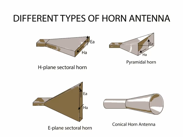
Precision Horn Antenna Design and Performance
Horn antennas are a cornerstone of microwave engineering, characterized by a flaring metal waveguide shaped like a horn to direct radio waves into a narrow, high-gain beam. This gradual transition from the waveguide to free space ensures an efficient impedance match, minimizing signal reflections and maximizing power transmission. Due to their high directivity and low loss, horn antennas are the gold standard for satellite tracking, radar systems, and as "gain standards" for calibrating other antenna types.
The specific geometry of the flare—whether pyramidal, sectoral, or conical—dictates the antenna's beamwidth and gain characteristics. Specialized designs, such as corrugated horns, incorporate internal grooves to improve pattern symmetry and reduce side-lobe levels, which is vital for high-precision applications like radio astronomy and deep-space communication. Often constructed from high-grade aluminum or brass with weather-resistant finishes, these antennas provide exceptional stability and performance across broad frequency bands.
Wideband Log Periodic Antenna Design
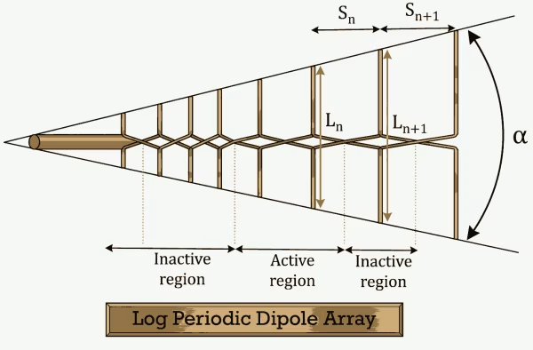
Log periodic antennas are uniquely designed to provide consistent performance over an exceptionally wide frequency range, often spanning several octaves. Unlike standard Yagi antennas, the dimensions and spacings of a log periodics dipoles follow a logarithmic progression. This geometry ensures that as the operating frequency changes, different elements of the array become active, maintaining a stable gain, feed point impedance, and front-to-back ratio across the entire bandwidth.
This frequency-independent characteristic makes the log periodic antenna an ideal solution for spectrum monitoring, surveillance, and multi-band communication systems. Typically constructed from high-durability materials like aviation-grade aluminum and mounted on a ruggedized boom, these antennas are built to survive extreme wind loads and environmental exposure. Their ability to cover multiple bands with a single feed line reduces equipment overhead while providing a high-gain, directional radiation pattern for mission-critical RF applications.
High-Gain Grid Parabolic Antenna Design & Diagram
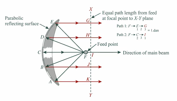
Grid parabolic antennas are engineered for long-distance, point-to-point communications where high gain and low wind loading are essential. By utilizing a perforated or mesh reflector rather than a solid dish, the design significantly reduces the surface area exposed to the wind, allowing for installation on lighter towers or in high-wind environments without sacrificing structural integrity. The precise parabolic curvature focuses RF energy into a narrow, concentrated beam, providing exceptional directivity and long-range connectivity for microwave backhaul and wireless networking.
The polarization of a grid antenna is easily adjusted by rotating the feed assembly or the reflector itself, typically supporting either vertical or horizontal orientations. These antennas are often constructed from heavy-duty, corrosion-resistant aluminum and finished with industrial-grade coatings to ensure longevity in coastal or extreme climates. With its high front-to-back ratio and excellent signal rejection from the sides and rear, the grid parabolic antenna is a highly efficient solution for minimizing interference in crowded spectral environments.
High-Performance Quadrifilar Helix Antenna Design & Diagram
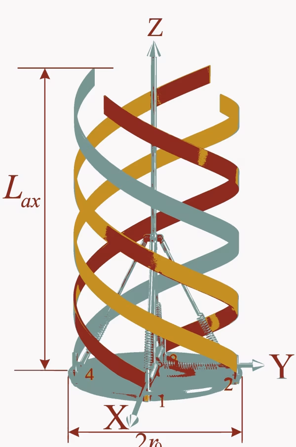
The Quadrifilar Helix Antenna (QHA) is a specialized circularly polarized antenna consisting of four equally spaced helical elements wrapped around a common cylinder. This sophisticated geometry is fed in a specific phase quadrature (0, 90, 180, 270 degrees) to produce a remarkably shaped radiation pattern, often referred to as a "cardioid" or hemispherical beam. This wide beamwidth allows the antenna to maintain a high-quality link with satellites from the horizon to the zenith without requiring a tracking system, making it the premier choice for GPS, GNSS, and weather satellite reception.
One of the defining advantages of the QHA is its exceptional axial ratio across a broad beamwidth, which effectively suppresses multipath interference and signal fading caused by reflections. Because of its resonant design, it does not require a large ground plane, allowing for a more compact and versatile form factor. Typically enclosed in a rugged, UV-stabilized radome, these antennas are built to deliver consistent, maintenance-free performance in tactical, maritime, and aerospace environments where reliable satellite-to-ground connectivity is paramount.
Precision Cavity Backed Spiral Antenna Design & Diagram
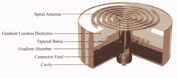
The cavity backed spiral antenna is a highly versatile, frequency-independent radiator known for providing exceptionally wide bandwidth and consistent circular polarization. By integrating a spiral conductive element with a metallic backing cavity, the design forces the antenna to radiate into a single hemisphere, significantly increasing forward gain and directivity. This configuration is particularly effective at maintaining a low axial ratio over multiple octaves, ensuring high signal integrity for applications involving complex signal environments and varying target orientations.
Designed for high-performance defense and aerospace applications, these antennas are often utilized in Electronic Warfare (EW), Radar Warning Receivers (RWR), and wideband SIGINT systems. The cavity is typically loaded with RF-absorptive material to suppress back-lobes and prevent internal reflections from distorting the radiation pattern, resulting in a clean, stable beam across the entire operating frequency. Compact and ruggedized, cavity backed spirals offer a low-profile solution that can be flush-mounted on aircraft or vehicles, delivering reliable wideband performance in the most demanding tactical scenarios.
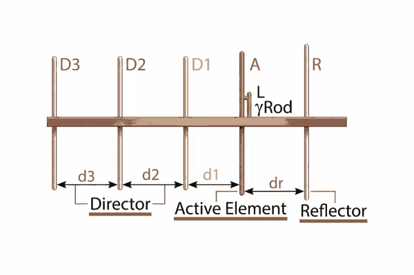
High-Gain Yagi Antenna Design & Diagram
The Yagi-Uda antenna, commonly known as a Yagi, is a highly directional radiator that achieves significant gain through the use of parasitic elements. The design consists of a single driven element—typically a folded dipole—accompanied by a slightly longer reflector behind it and one or more shorter directors in front. This configuration focuses the electromagnetic energy into a narrow beam, providing excellent front-to-back ratios and high selectivity, which is ideal for point-to-point communication and long-distance signal reception.
Precision in element spacing and length is critical to the Yagi's performance, as these factors determine the antenna's center frequency, bandwidth, and gain characteristics. Modern Yagi antennas are often constructed from heavy-duty, weather-resistant aluminum alloys and utilize stainless steel hardware to ensure long-term durability in extreme environments. Because of their lightweight yet rugged architecture, they are widely deployed in VHF/UHF telecommunications, tactical military links, and amateur radio applications where a high-gain, directional solution is required.
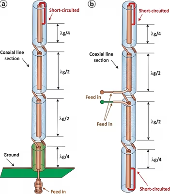
High-Performance Fiberglass Collinear Antennas Center-Fed & End-Fed
Fiberglass collinear antennas are engineered for superior omnidirectional coverage, making them a preferred choice for base station applications in demanding RF environments. These antennas consist of multiple dipoles stacked vertically and fed in phase, which compresses the vertical radiation pattern to concentrate energy toward the horizon. This design significantly increases gain without requiring a larger horizontal footprint.
Housed in a high-intensity, UV-stabilized fiberglass radome, the internal radiator is protected against harsh weather, wind loading, and corrosive atmospheres. The collinear architecture ensures a low angle of radiation and consistent impedance matching across the operating band, providing a reliable, long-term solution for mission-critical communication networks.
